
Minimizing the Risk of Component Damage During a Flex Circuit
Risk of Component Damage During a Flex Circuit
Flex circuits are designed to bend and reshape themselves during operation. This means the circuit must be made with materials that can handle the stresses and forces involved in dynamic bending. Otherwise, it may suffer from delamination or other damage that can lead to failure. How do you minimize the risk of component damage during a Flex circuit? Here are a few tips to keep in mind.
The most important thing to do is ensure that the drill-to-copper distance in a flex PCB is at least 8 mil. This ensures that copper can withstand the stresses and contractions of a flex circuit’s movement. It also helps reduce delamination, which can happen when the copper layer separates from the rest of the flex circuit. This is caused by stress and temperature changes, which can occur when the flex circuit is exposed to heat or vibrations.
It is also important to ensure that the pads and landing terminations on a flex circuit are well-fletched. This will help to decrease the stress on them when bending occurs and it will also make soldering much easier. The best way to do this is by using a pad fillet, which will spread the stress out and reduce the chance of cracking or peeling.
Another crucial factor to consider when designing a flex circuit is the minimum bend radius. This is the smallest amount of curvature that the flex circuit can tolerate without damaging the copper or having other issues. The minimum bend radius should be determined early in the design process so that it can be incorporated into the layout.
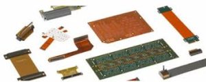
Minimizing the Risk of Component Damage During a Flex Circuit
In addition, it is a good idea to use rigid-flex instead of traditional multilayer PCBs when making a flex circuit. This will reduce the number of connections and allow for higher wiring density and a smaller footprint.
Lastly, it is important to use an appropriate solder mask and coverlay material for a flex circuit. This will help to protect the circuit from environmental conditions and prevent delamination, which can be caused by moisture or other factors that affect a PCB’s reliability. The best options for a flex circuit include solder masks that are resistant to etching, pressure-sensitive adhesives (PSA), and conductive epoxy.
One of the most common causes of component damage in a flex circuit is the failure of the circuit’s copper pads. This can be caused by a variety of reasons, including poor soldering techniques, high temperatures, or mechanical flexing. To avoid this problem, it is important to use a high-quality solder paste, and ensure that the pads are properly sized and spaced.
In addition, a good solder mask will prevent copper oxidation and extend the life of a flex circuit. Finally, it is a good idea to use a high-quality coverlay that will protect the traces and pads from external interference.
The above tips will help you create a successful flex circuit that can withstand dynamic bending and vibrations. They will also increase the quality of your final product. To learn more, contact us at Qflex, a leading flex circuit manufacturer serving the Aerospace/Defense, Medical, Semiconductor, and Industrial sectors.