
How do flex pcb board techniques vary for flexible circuit boards?
flex pcb board techniques vary for flexible circuit boards
When designing a flex circuit board, it’s important to know how various techniques vary. For example, the bending radius can significantly impact the longevity of the board and must be determined early in the design process. Also, routing in bend areas must be carefully planned. Traces should be routed perpendicular to the bend lines, and vias and pins should be excluded from those areas in order to prevent damage. Lastly, it’s best to avoid stacking layers with traces running adjacent on top of each other in a bend area; stagger the traces instead.
The thickness of the copper trace impacts a flex circuit’s flexibility. Thicker traces are less flexible and can damage the board when bent. The thickness of the dielectric film used in flex circuit boards can also affect flexibility. Thicker dielectrics, like FR-4, are more rigid and less pliable than thinner ones. The etch patterns that are used in flex circuits can also impact the flexibility of a board. The use of a narrower etch pattern in the signal layer can help to increase flexibility.
For a flex pcb board to be successful, it must be able to withstand multiple bending cycles without damaging any of the components. It’s important to determine the optimum bending radius for the circuit during the DFM (Design for Manufacturing) process. In addition, a stiffener can be added to the end of the flex circuit if necessary. A stiffener can be a bead of epoxy, acrylic or hot-melt glue that will improve the longevity of the flex circuit when it exits the rigid board. However, dispensing and curing these liquids can add labor and time to the production process.
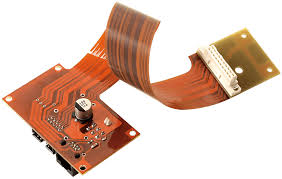
How do flex pcb board techniques vary for flexible circuit boards?
Stiffeners can be a good option for high-density designs that require more bending cycles than a single-sided flex PCB can handle. In some cases, they can even be incorporated into the rigid-flex section of a circuit. It’s important to communicate with the manufacturing and assembly engineers about these options when designing a flex circuit to ensure they understand the requirements of the design.
Flex materials are more prone to movement and contraction during manufacturing, so it’s important that the drill-to-copper distance be at least 8 mils. It’s also a good idea to decide whether panel plating or pad-only-plating (button plating) is preferred for the flex circuit. Button plating allows manufacturers to better manage copper thickness and improve etch yields in small etch patterns, but it requires more processing steps.
Lastly, the choice of an adhesive is also critical. Acrylic or epoxy adhesives are typically used for flex circuits, although pressure-sensitive adhesives can be used for some applications. The adhesive needs to be durable enough to withstand heat and mechanical stress, so choosing the right type of adhesive is important for reliability.